SEE Electrical PLM软件:用于电气产品生命周期管理的模块化软件套件(PLM – 产品生命周期管理)。产品生命周期管理(PLM)产品从需求开始,经过设计、制造服务和废弃的全生命周期。
在电气设备领域,PLM软件安装包允许功能(从系统框图到接线图)与安装(从空间预留到三维线束)并行开展设计。随着项目成熟度的不断提高,设计数据会不断迭代和变化,这个过程需要复杂的工具进行管理。
SEE Electrical PLM提供模块化和完整的软件套件,用于各类车辆或工厂的复杂电缆配置和生命周期管理。
SEE Electrical PLM满足了完整工程过程的需求,从需求管理到接线图自动生成,这些都在一个数据库中并行运作。
拓扑方式允许综合系统设计和3D空间预留。此外,还能够管理电气线束配置和生命周期。
SEE Electrical PLM能够连接到SEE Electrical Harness Manufacturing进行电气线束加工。
他们用 SEE Electrical PLM

SEE Electrical PLM modules
Discover SEE Electrical PLM’s different packages and modules!
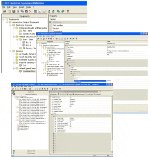
Equipment catalogue definition with SEE Electrical Equipment Definition
Equipment Definition– Main attributes
– Part Number, manufacturer
– Description…
– Equipment connectivity
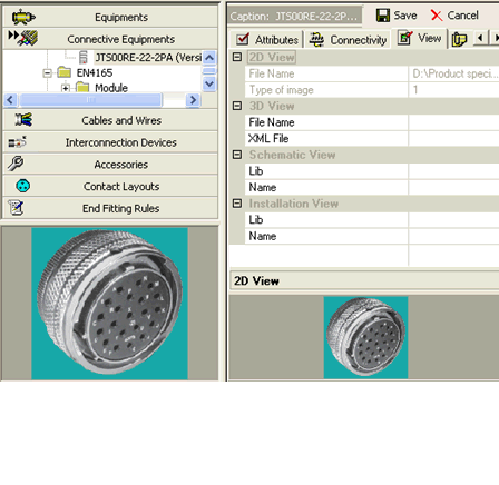
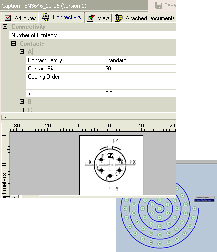
Connective Equipment Definition– Connectors, Nb pins, type, gauge
– Type, series
– Pin grouping
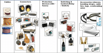
Wires and cables– Cable type (Shielded, Twisted, Coax…)
– Wire attributes (Color, gauge…)
– End fittings (Contacts…)
Functional electrical devices list management with SEE Device Manager
Management of list of functional electrical devices used by the products (plane, car…)– Equipment Identification ( functional group, tag, .. )
– Design Solution of Equipment devices (configuration)
– Equipment Part Number from See EED ( = specific supplier reference)
– Equipment connectivity
•Connectors
•Pins
Assign Equipment devices to the functional decomposition
Management of technical solutions • Definition of Equipment devices used in the final product.
• Management of variants (Configuration).
• By Integration Center (Panel/Rack)
Check consistency between Functional Equipment and Installed Equipment• Access to Equipment List during Functional Design and Installation Design.
Assign Connective devices – Management of technical solutions • Definition of Connective devices used in the final product.
• Management of variants (Configuration).
• Pin Booking…
Project management with SEE Project Manager PLM
SEE Project Manager PLM is a product dedicated to the management of your electrical projects created with SEE software applications.
Designed for teamwork, SEE Project Manager PLM is perfectly adapted to small, medium and large companies. It centralizes and secures all your electrical data, integrating a “Vault” or “Safe” – type management in a native way.
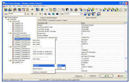
SEE Project Manager PLM organizes the entire electrical data flow that allows a better communication and coordination between different departments and work teams within your company (research department, Maintenance department, Purchasing department, etc.). SEE Project Manager PLM also shortens design deadlines.
SEE Project Manager PLM allows a product management in a collaborative context,
SEE Project Manager PLM ships with a default database, which will allow you to become operational instantaneously and will adapt very easily to your need, as they evolve.
According to the kind of the organization, you will be able to manage one (or several) databases containing your electrical projects.
Block diagrams / Functional diagrams definition with SEE Electrical Expert
As for wiring diagrams SEE Electrical Expert is used to manage principle diagrams.
It manages:
• Link to SEE Electrical Equipement Definition to select equipment
• Connectivity between equipment
• Definition of net groups (to be use by Topology)
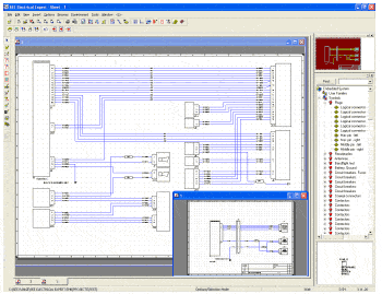
Creation and modification of diagrams– Multiple sheets project management (off page referencing).
– Dedicated tools for signal insertion, symbols.
– Wires are cut automatically.
– Windows drag and drop, cut and paste and undo features, context menus, icon bars…
– Manual or automatic tagging of components.
– Real time management of cross-references (Multiple pages).
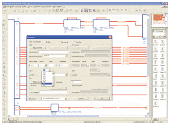
Complete management of connectors– Automatic connector insertion.
– Part number selection.
– Automatic numbering of connector pins according to part number.
– Management of all type of pins (contact, socket…).
– Real-time control (pin duplication, exceeding capacity, etc.).
– Pins management, swap pins, spares.
– Management of connector composition (backshells, pins and accessories).
– Management of inline connectors (Automatic pin numbering…).
Management of signals, wires, cables and shielding– Real time management of signal networks. (nets)
– Management of cable and wire numbers, gauge, colour…
– Management of cable types (shielded, twisted, coax…).
– Selection of cable and wire part numbers.
Report generation– Automatic lists generation of:
– Equipment lists,
– Wire lists,
– Cable lists,
– Manufacturing lists, etc…
Symbol libraries:
– Included symbol libraries of international standards such as ATA, BNAE, DOD-STD-863B…
Symbol editor:
– create, modify and organize symbol libraries.
Working methods:
Management of working methods according to standards.
Equipments, connectors, signals, wires and cable numbering.
Connectors, cables graphical representation.
Title blocks and page formats management.
Exchange and CommunicationGraphic formats
DXF/DWG, BMP, JPEG, TIFF, PCX, SVG,CGM…
Data exchange formats
XLS, DOC, HTML, XML …
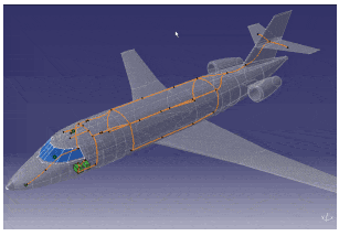
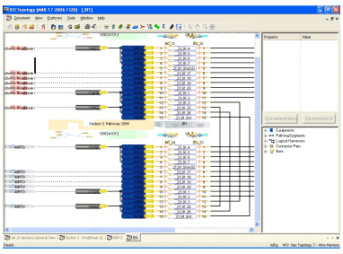
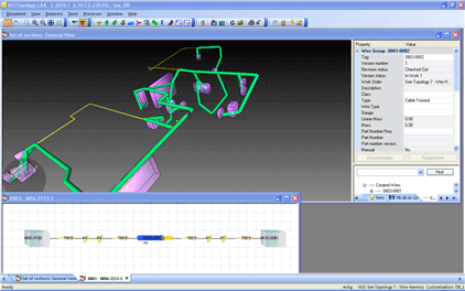
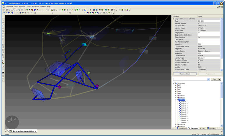
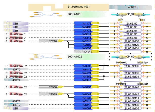
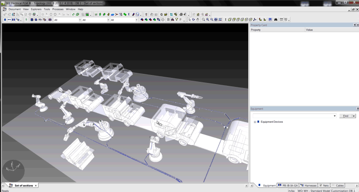
Electrical harness creation / wire routing with SEE Topology
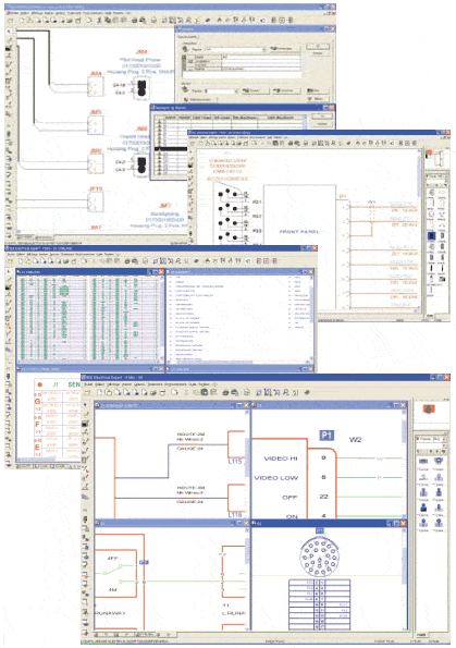
Interactive design and modelling of logical cabling and harnessing.
The Topology module allows the definition and modelling of wiring and harness systems as the result of Systems Integration process and 3D electrical installation.
Automatic wiring diagrams generation with SEE Generative View
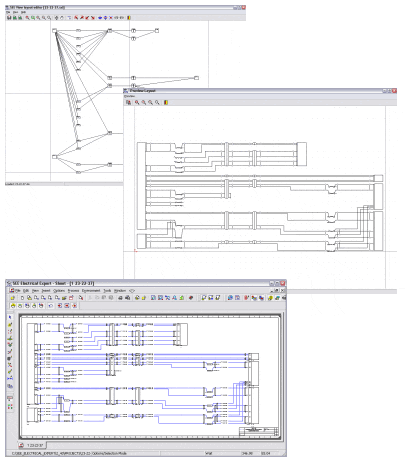
SEE Generative View allows to generate wiring diagram gathering information from the database, using logical harness data created by the Topology and Topology Viewer modules.
Drawings are then generated into SEE Electrical Expert.
This package is very efficient for troubleshooting or engineering review.
Physical Harness solutions calculation with SEE Harness Manager
A physical harness results of the combination of:
•the wiring list of a harness (cables and connective devices, end-fitting)
•the geometry and mechanical accessories of a geometrical harness (branches with their geometry, protections, splice zones, accessories)
The physical harness calculation computes:
•The length of the cables, by routing them into the GH branches
•The branches diameter, due to cables and protections
•The harness characteristics such as mass, cost, gravity center, number of elements
•The bill of material of the harness
At release time, a PH part number is computed by automatic comparison with the other PH solutions
Change and configuration management with SEE Hub Application Server
Services and Data Management -Configuration Management
•Design several Systems / Installation / Harness alternatives
•Optimize re-use between alternatives
– Change Management
•Control all modifications applied to the database (security)
•Organize user tasks in Workflows (concurrent engineering)
•Keep track of all modifications (history tracking: who & when)
– Other standard PDM functionalities:
•Life-cycle management: keep track of design maturity
•Versioning: keep track of design evolutions
•Data Locking: Lock data during modification to avoid concurrent access
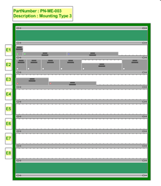
Equipment assignment to equipment centers (panels, bays, etc.) with SEE Logical Installation Design
Define Location of Equipment Devices • By Product structure
• By Integration Center ( Pannel/Rack)
Inside Equipment center, assign Equipment ports to ports of Equipment center
Pre-Position equipment devices into: • Equipment Center
• Disconnect brackets
Send requirement to 3D Installation designer. • List of Equipment for 3D Installation design.
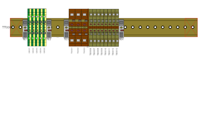
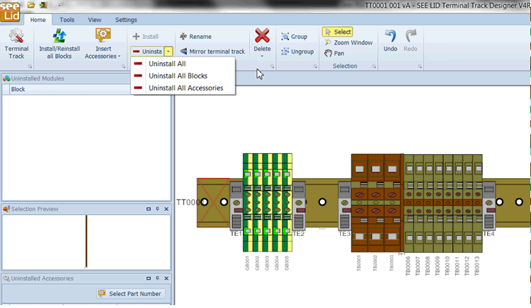
Design physical organization of Terminal Track • Selection of the Terminal Track Part-Number
• Add accessories (Cover plate, Terminal stop, … )
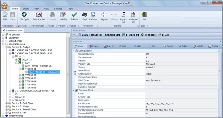
Inline connectors pin booking definition & Pin Allocation Management with SEE Connective Device Manager
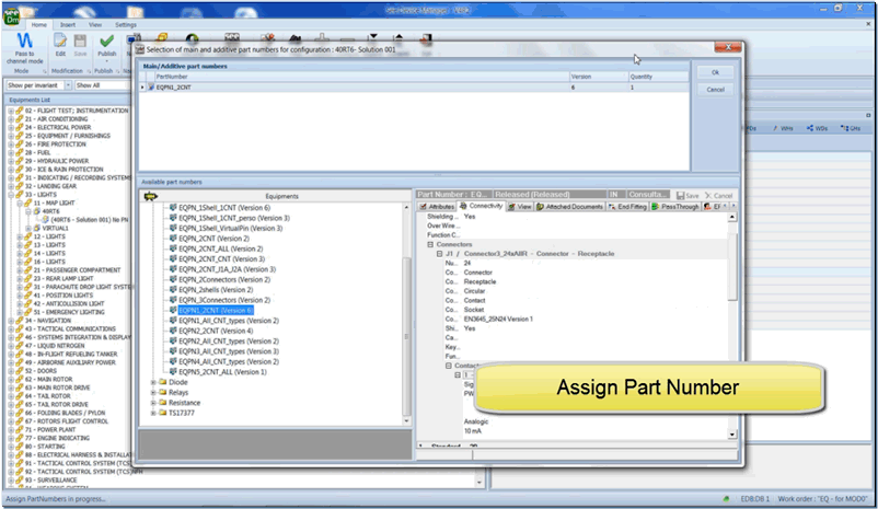
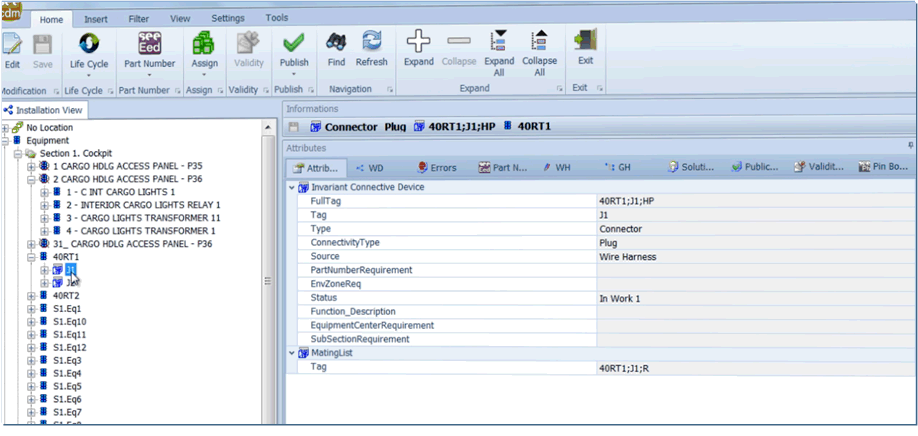
Manage solutions/versions of connective devices.
Desynchronize design of solutions from the design of the wire harnesses/wiring diagrams
• Manage the position of the connective devices in the installation (location, installation device on which it is mounted)
• Provide pin booking tool
• Provide a Connective Devices Browser to help users of all applications to select connective devices
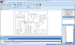
Harness documentation and flattening with SEE Electrical Jigboard
2 modes:
– “documentation”: create 2D drawing harness documentation – compare versions – insert wire grids and BOM (Bill of Materials) etc.
– “jigboard”: create the formboard on scale – compare versions – insert wire grids and BOM (Bill of Materials) – manage prededined formboard tables layout etc.
 如果您对此感兴趣,欢迎问问展商吧!
 暂无数据
暂无数据 暂无数据
暂无数据 如果您对此感兴趣,欢迎问问展商吧!